BIM modeling
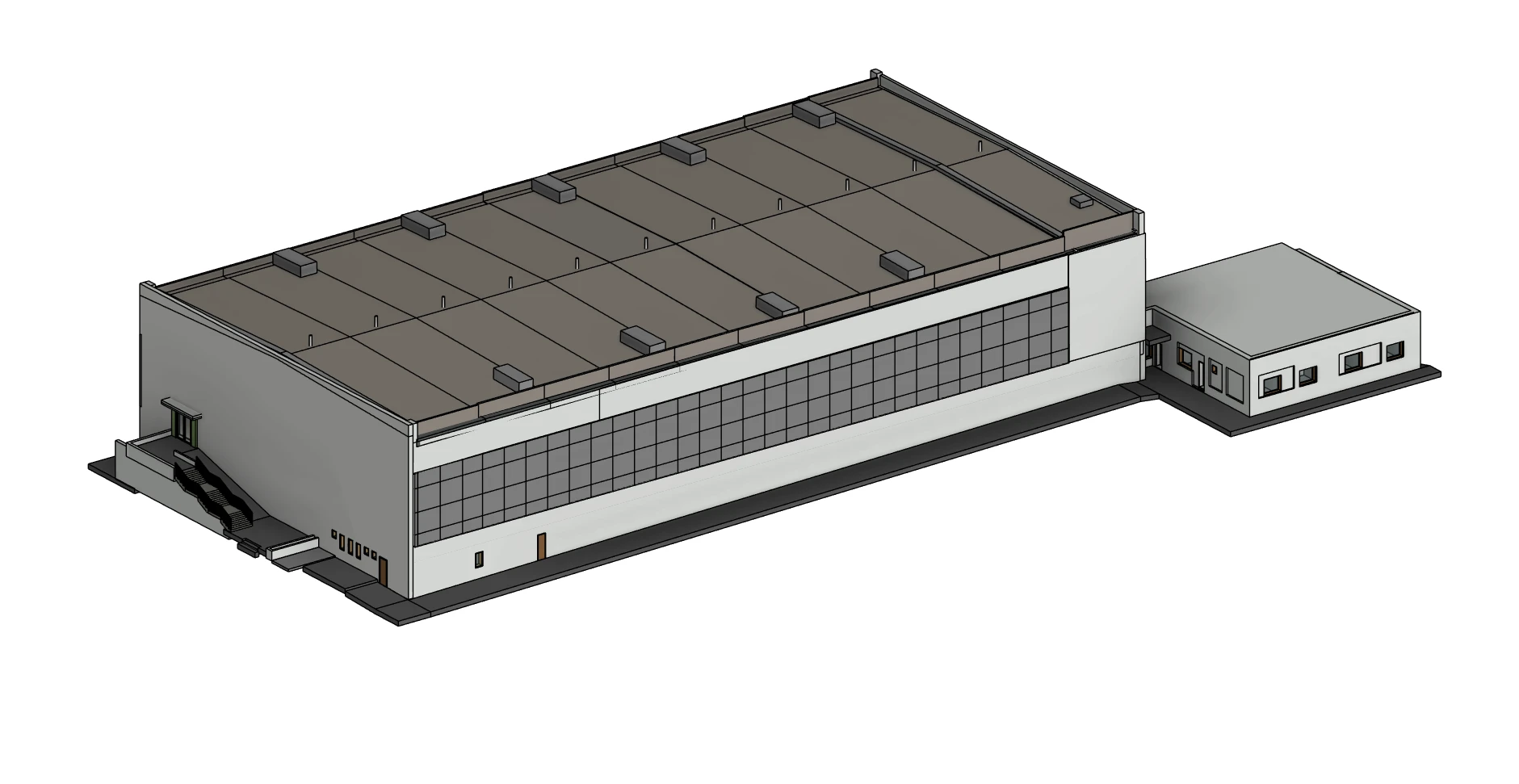
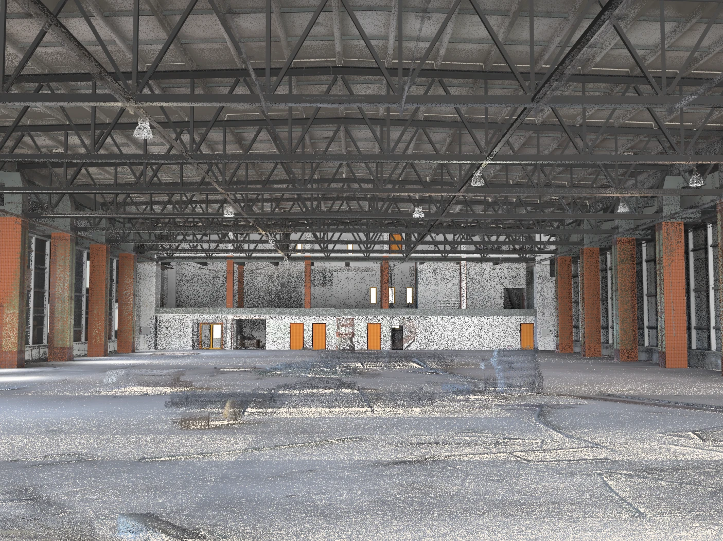
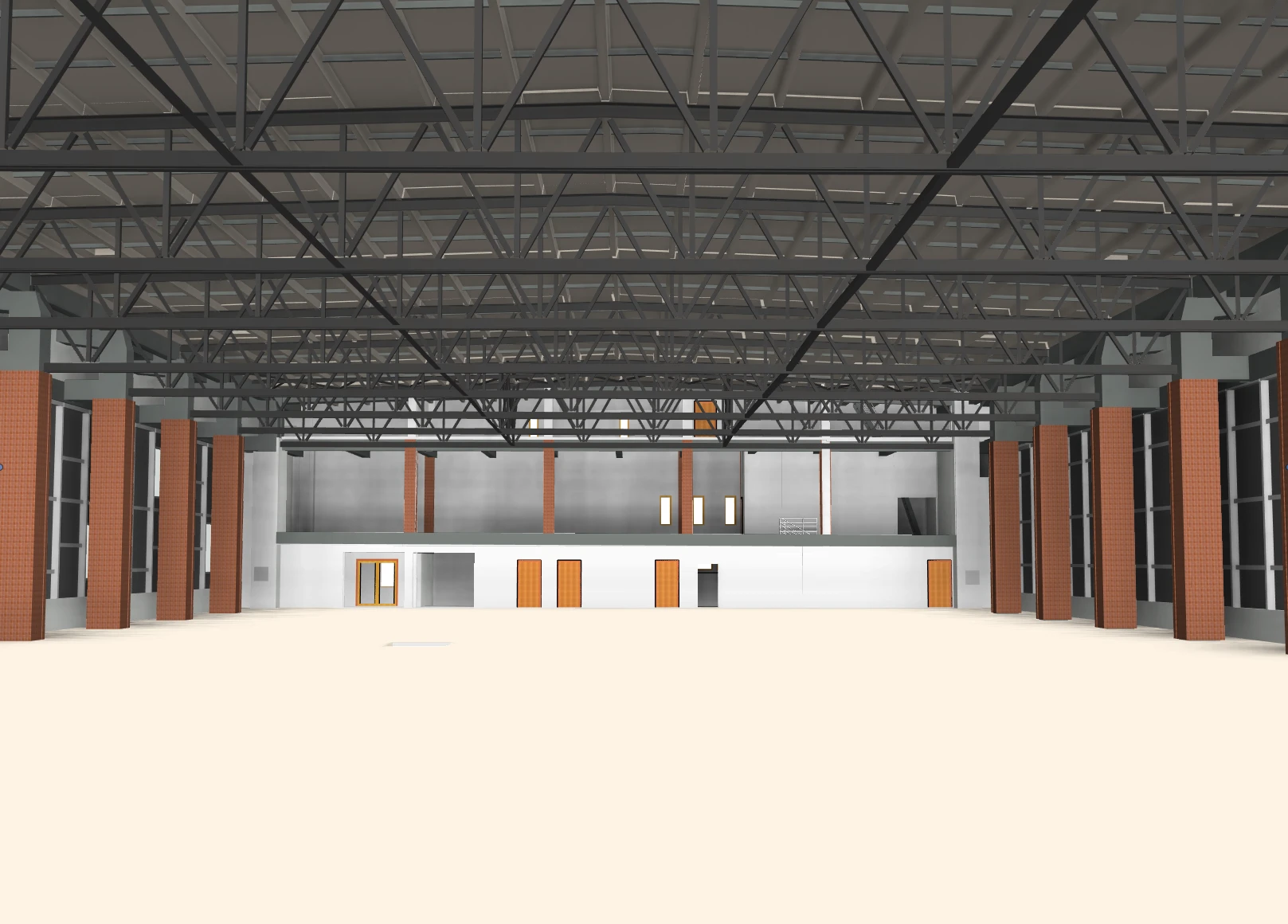
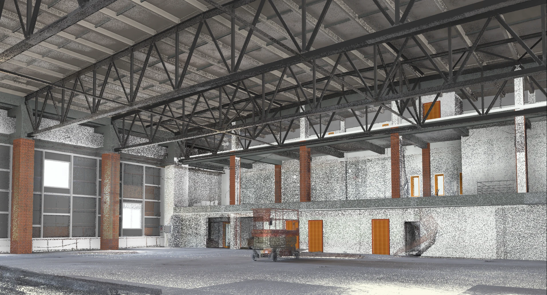
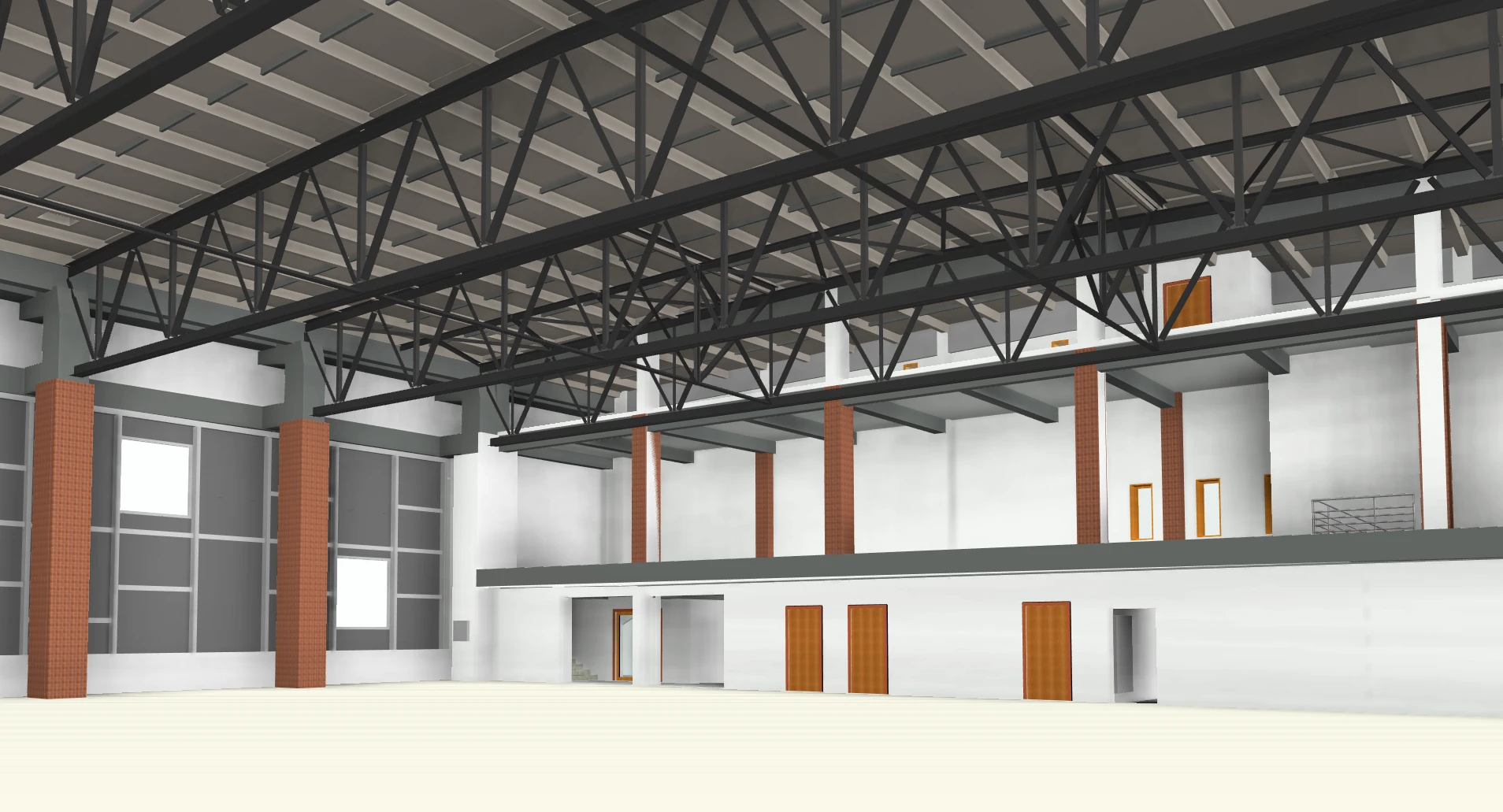
BIM (Building Information Modeling) is a digital representation of a building’s physical and functional characteristics. Through Scan to BIM, we convert laser scan data into accurate 3D BIM models, providing architects, engineers, and facility managers with a reliable foundation for design, renovation, or asset management. Our models capture real-world conditions with high precision, streamlining project workflows and reducing costly errors.
\
Comparison table
| LOD Level | Level of Development (Overall Definition) | Level of Detail (Geometry) | Level of Information (Data) |
|---|---|---|---|
| LOD 100 - Conceptual Design | The model element may be graphically represented with a symbol or other generic representation, but does not satisfy the requirements for LOD 200. Information related to the model element can be derived from other model elements. | Conceptual / Symbolic: Elements are not geometrically representative. They are placeholders to indicate existence, often as a 2D symbol or a conceptual mass. | Analysis-based: Information is derived from analysis, such as cost per square foot, area calculations, or overall project phasing data. No specific element data exists. |
| LOD 200 - Schematic Design | The model element is graphically represented as a generic system, object, or assembly with approximate quantities, size, shape, location, and orientation. | Generic / Approximate: Elements have recognizable shapes but are not specific. A wall is a wall, but its material composition is not defined. A pump is shown, but it is a generic representation, not a specific model. | Generic placeholders: Information is attached but is not manufacturer-specific. Examples: "8-inch Concrete Slab," "Generic Chiller," along with basic performance specifications. |
| LOD 300 - Detailed Design | Clearly defined geometry matching real dimensions; moderate visual detail (e.g., door swings, window frames). | Specific / Precise: The geometry is precise and accurate. The model represents what will be built. For a wall, this includes its exact thickness and material layers. For equipment, it's the specific size and connection points of the chosen model. | Specific data: Information is specific to the chosen system or product. Examples: "Armstrong Optima 2'x2' Ceiling Tile," "Taco Model KV1504 Pump," including manufacturer, model number, and material specifications. |
| LOD 350 - Coordination & Clash Detection | The model element includes the same detail and information as LOD 300, but adds parts necessary for coordination with adjacent or nearby elements. | Coordinated Assembly: Includes geometry for interfaces, connections, and supporting elements. For example, it would show hangers for ductwork, supports for pipes, or the specific interaction between a beam and a column. | Interface & coordination data: Information about connections, clearances, and relationships with other building systems. E.g., required access clearances for maintenance, support bracket specifications. |
| LOD 400 - Fabrication & Assembly | The model element is graphically represented as a specific assembly, with complete fabrication, assembly, and detailing information in addition to quantity, size, shape, location, and orientation. | Fabrication-Level Detail: Includes all the detail necessary to manufacture the component. This is equivalent to a shop drawing. It may include details on welds, fasteners, reinforcements, and assembly sequences. | Fabrication & ordering info: Detailed information required for fabrication and procurement. This includes part numbers, supplier details, material specifications, and any specific finishing or treatment instructions. |
| LOD 500 - As-Built & Facilities Management | The model element is a field-verified representation of the constructed assembly in terms of size, shape, location, quantity, and orientation. | As-Built / Field-Verified: The geometry has been verified in the field to represent the true, final, installed condition. It is not necessarily "more detailed" than LOD 400, but it is verified as accurate. | Operations & Maintenance (O&M) data: Information is for facilities management. Examples: Installation date, warranty information, serial number, link to O&M manuals, maintenance schedules, and replacement part numbers. |
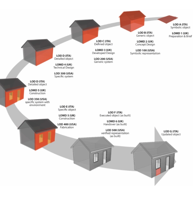
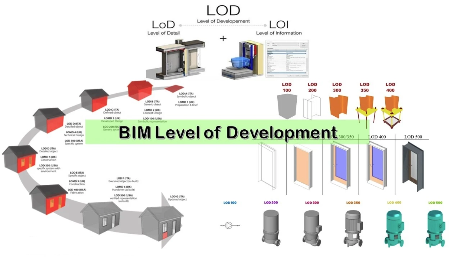
Level of Development (LOD) defines the reliability and usability of a model element at a specific point in the project. It indicates how accurate, complete, and dependable the information is for decision-making, coordination, or construction. It includes both the geometry and the associated data (e.g., dimensions, material specs, performance requirements). It is a standardized framework used for contracts and project milestones.
Levels of Detail (LOD):
-
LOD 100 – Conceptual: A basic massing model with overall shape and size; used for early design and feasibility studies.
-
LOD 200 – Approximate Geometry: Elements are represented with approximate size, shape, and location; useful for schematic design.
-
LOD 300 – Precise Geometry: Accurate size, shape, and placement of building elements; suitable for coordination and documentation.
-
LOD 350 – Detailed Coordination: Includes connections and interfaces between systems; supports clash detection and constructability reviews.
-
LOD 400 – Fabrication-Ready: Contains sufficient detail for fabrication and installation; used by contractors and fabricators.
-
LOD 500 – As-Built: Field-verified model reflecting exact built conditions; ideal for facility management and future renovations.
Level of Detail refers only to the graphical or geometric complexity of an element in the model—how much visual or shape-based information is included. It doesn’t account for the usefulness or accuracy of that information. For example, a model element can be very detailed graphically but still not reliable for construction or fabrication (e.g., it may look realistic but not match the actual dimensions or specs).